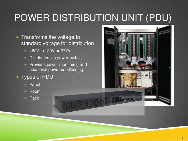
If you go to most server rooms, you'll see things that resemble deluxe electric power strips except the gender looks reversed. These are called Power Distribution Units. Depending on the features purchased, they can have lots of advantages over regular power strips.
 However, there is a MAJOR problem with many of the PDU units I have seen. The female patch cords wiggle out MUCH easier from a PDU port than a typical household 3-prong 110v male cord. Over time, the problem can become so bad that a casual brushing against a cord can be enough to cut power. To address this problem, many interesting solutions have appeared in the market.
 One product is a metal retaining clip, as offered by a company called Geist. Provided that the PDU and cords are the exact model, it looks like these clips may work. If clips need to be purchased after a PDU is purchased, the company provides photos and measurements. Both of those makes the odds of ordering the correct clip much higher. Some PDUs also have holes installed on the side to make securing clips a bit easier. However, many legacy PDUs usually lack holes or even a ledge for such clips to grab. Also, the patch cord strain relief apparently needs to be ribbed to work.

So much for the solutions that didn't work for me. Here's one solution that did. The solution needed to be cheap, be able to install without turning off the equipment, be non-conductive and allow the cord to later be unplugged or re-secured easily and quickly. The result is the plastic clip below.
The clip works with commonly available materials typically found in a data center. In addition to the clip, you'll need some Zipties, Velcro and some small stubby screws and washers. Here's how it works, Put one Ziptie through the clip slot. Then add additional Zipties to reach around the PDU. Slide the clip on the cord. Then use the head of another Ziptie to complete the chain of ties. Velcro wraps around the cord which allows the clip to work if the strain relief isn't an exact fit.

Below is a photo of a clip securing a patch cord to a PDU. If the cord needs to be unplugged, just undo the Velcro then slip the cord out of the clip. When the cord needs to be re-secured to the PDU the clip is pressed back on the cord then re-wrapped with the Velcro. By using this solution, a convenient cord securing solution can be installed with zero downtime.

The PDU clip was printed in HIPS plastic. Other parts are commonly available at a typical hardware store.
The printable clip is downloadable HERE.
If you find this design helped you secure some PDUs or if you have a suggestion on how the idea can be improved, let me know!


