Sunday, October 21, 2012
Why do open source hardware?
I haven't posted lately. This is due to other non-technical things in my life getting in the way of doing cool stuff. Fortunately, the projects featured on this blog are open source. That means world progress doesn't need to stop simply due to poor time management skills on my part. That is just one advantage to open source hardware! I ran across a good video that shows some other advantages as well. Enjoy!
Tuesday, May 22, 2012
Adding Ethernet capability
Adding Ethernet capability I really like devices that can be controlled over a network. So, a natural add-on to this project is an Ethernet shield. This capability could eliminate the need for readouts and possibly physical controls. I discovered that there are several different Ethernet options all with different costs and benefits. Some boards are simply expansion shields while others apparently have features that don’t even require a controller board! Here are the options I considered.
Once it arrived, I first tried loading the example web server code that came with the latest Arduino editor. I had no luck making the example code work. The example apparently expected another board type. So, I visited the ekitszone site to see if they had a different library that should be used. They did.
After downloading the ZIP, I unzipped the file into the \libraries directory and moved the examples directory to the proper place.
After some trial and error, I finally got an Arduino board to spit out the webpage below.
 The HanRun Ethernet board was tested with....
XP professional SP3
Arduino editor 1.0.3
Two board types were tried. They were:
-A genuine Arduino Uno
-An Arduino Duemilanove compatible called the Freeduino
Thanks to Google Drive, I can also provide the specific files used for testing
The above webpage was generated using this sample sketch HERE.
A copy of the Ekitzone library file required for the above example (which now appears to be rarer than hen's teeth) can be downloaded HERE
Due to working with XP, I can only use version 1.0.3 . Higher versions don't seem to allow XP to upload sketches to boards.
There seems to be quite a bit of code used to write out a web page. So, making the assembly do things other than displaying static web pages may be a bit of a challenge.
 One easy way of matching Ethernet with an Aurduino is simply to buy a unit with Ethernet already built onto the board (over $50). I'm sure it's nice & probably works right out of the box.
 - The more expensive “shields” have advanced features. Once feature is to use DC from a POE capable switch. If the feature is present, these higher-end switches can configure ports to provide (48v DC - usually 15W max) which can be used to power end devices. Usually, this is a feature only found on commercial switches.
- Then there are the really cheap Ethernet “shields”. Their main advantage seems to be price ($15-$25). They are lower cost but more complex to program than the higher cost W5100 based shields. Here is a good article that explains the differences in the ENC28J60 board varieties.

Once it arrived, I first tried loading the example web server code that came with the latest Arduino editor. I had no luck making the example code work. The example apparently expected another board type. So, I visited the ekitszone site to see if they had a different library that should be used. They did.
After downloading the ZIP, I unzipped the file into the \libraries directory and moved the examples directory to the proper place.
After some trial and error, I finally got an Arduino board to spit out the webpage below.

XP professional SP3
Arduino editor 1.0.3
Two board types were tried. They were:
-A genuine Arduino Uno
-An Arduino Duemilanove compatible called the Freeduino
Thanks to Google Drive, I can also provide the specific files used for testing
The above webpage was generated using this sample sketch HERE.
A copy of the Ekitzone library file required for the above example (which now appears to be rarer than hen's teeth) can be downloaded HERE
Due to working with XP, I can only use version 1.0.3 . Higher versions don't seem to allow XP to upload sketches to boards.
There seems to be quite a bit of code used to write out a web page. So, making the assembly do things other than displaying static web pages may be a bit of a challenge.
And now for something completely different - the Freeduino!
 Assembling the first piece - a Freeduino
A while back, I attended the Syracuse Hackerspace event where they were introducing users to the magic of soldering together micro-controllers. I met some nice people, soldered my project and generally had a good time. At the end, I had a really cool looking board. I figure combining this technology with a 3-D printing part or two may allow me to make something really cool.
Unfortunately, I didn't get any documentation with the board. Fortunately, it's well documented online. Looking at the origins of the board, the words Freeduino v 1.22 appear on the board. After some investigation, I found this was equivalent to a Duemilanove model (pictured to the right). I also found a guide which shows how it's soldered together.
Unfortunately, I didn't get any documentation with the board. Fortunately, it's well documented online. Looking at the origins of the board, the words Freeduino v 1.22 appear on the board. After some investigation, I found this was equivalent to a Duemilanove model (pictured to the right). I also found a guide which shows how it's soldered together.
The development kit software can be downloaded which includes a mini program that makes an LED flash. The software and tutorial are available at: http://arduino.cc/it/Guide/Windows
There are several other board versions such as Nano and Diecimila which have slightly different layouts. The Freeduino 1.22 has two main advantages over the other boards. First, it’s rather inexpensive. Second, it has adapters that allow “shield” boards to be added for extra functions such as temperature sensors, GPS sensors and such. The adapters work with . A good assortment of add-on shields can be seen at http://sparkfun.com.
 As for powering it, the board can draw from a standard USB cable or by a 7 to 12 volt DC adapter. Powering the board by either method is set by a jumper.
I downloaded the latest version of the software (version 1.0) from the Arduino website. Once the zip package of software was downloaded, I extracted it to it’s own directory (c:\Ardunio1.0). There was no need to run an "install" program. Just click to run the executable.
 Then came the time to decide what firmware I should use. Here's how I found the pedigree to match the firmware to. I observed that the main chip has markings of… ‘atmega328p-pv’ . Looking on the sofware menu, I noticed that this is also known as a “Duemilanove”.
Then, I followed the instructions below for installing the driver:
When you connect the board, Windows should initiate the driver installation process (if you haven't used the computer with an Arduino board before). On Windows Vista, the driver should be automatically downloaded and installed. (Really, it works!) Start à Control Panel à System and Security à System à Device Manager. You’ll see the UNO. Update software driver à Point to the driver’s folder that was created with the installed softare.
On Windows XP, the Add New Hardware wizard will open:
- When asked Can Windows connect to Windows Update to search for software? select No, not this time. Click next.
- Select Install from a list or specified location (Advanced) and click next.
- Make sure that Search for the best driver in these locations is checked; uncheck Search removable media; check Include this location in the search and browse to the drivers/FTDI USB Drivers directory of the Arduino distribution. (The latest version of the drivers can be found on the FTDI website.) Click next.
- The wizard will search for the driver and then tell you that a "USB Serial Converter" was found. Click finish.
- The new hardware wizard will appear again. Go through the same steps and select the same options and location to search. This time, a "USB Serial Port" will be found.
From here, the website instructions get a little confusing. It specifies picking out a COM port. Now for me, when I think of COM ports, I think of serial devices. However, this board is a USB device. Then remembering my A+, I recalled that not unheard of to have a USB device work as a COM resource. As an example, there is a product which allows a USB dongle to act like a serial device. It was for computers that had no serial ports. Once plugged in, it provided an instant serial port! The Arduino board apparently is being used in that way too.
 So, here’s how to tell what COM port the USB device is using. Start the Device Manager MMC and scroll down a bit. There will probably be a “PORT” on COM3 used by a USB device. Chances are, that’s our device!
Once the COM is known, set it in the Arduino software by going to Tools à Serial Port
Now, let's check if the board was assembled OK. Time to upload a test file! Go to FILE then Examples. A program appears in the main window called LED flash. Then select FILE then Upload. It will automatically compile the sketch, upload the sketch, then start it. The whole process takes about 15 seconds. If all goes well, the sample program will start and the on board LED will start blinking.
Now that the basic board is operational, the next post will show how to add an additional shield we'll need for this project.
Monday, March 28, 2011
Installing the Makerbot Stepstruder upgrade on the Cupcake Ultimate (now called a CUPTHING)
Oh boy, upgrading to a MK6 stepstruder was an adventure. It would be nice if future versions of ReplicatorG would have support for cupcakes upgraded with a MK6. However, for those who can't wait for a pre-configured edition of ReplicatorG to appear, here's how you can upgrade right now! Given that you have the MK6 upgrade kit and three long bolts to mount the stepper board above the extruder board, you should have everything else provided by the kit. Here are the general steps I followed:
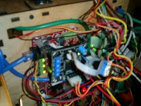 For mounting, I recycled my DC bracket I used for the earlier H-bridge problem. Fortunately, the boards were practically the same size. As for standoffs, I found using 6/32 screws with cut tubing for standoffs works well. Don't bother buying tubing. You can use a bit of tubing that comes with the makerbot reel holder.
 Wire-wrapped connections should be wired to make the equivalent circuit as described in this diagram HERE. If you're lucky enough to have some ribbon cable with with dip connectors on each end, cut the ribbon cable in half, then glue the two dip connectors together with superglue. The pins plus the use of a wire-wrap tool make a nice break-out box. That way, there is no soldering needed plus it's easy to troubleshoot and correct if the pin-outs are wrong. I also found using the edge of a 6 pin connector on the extruder's 3 pin connector is easier than soldering together a 3-pin connector to ribbon cable. Also, by accident, I discovered getting pins 7 & 8 reversed makes the circuit act like the motor has either noise problems or a firmware problem. Once I discovered that, I got out the wire wrap tool and was able to quickly correct that connection. Since then, I've had NO noise problems!
Now, for the software changes. I'm using Ubuntu Linux 10.10 with a downloaded version of ReplicatorG ver.24 . Also, remember to make sure you're using JAVA 1.5 and Python 2.5. There are several really handy pages to refer to:
http://wiki.makerbot.com/stepstruder-mk6-with-gen3
http://wiki.makerbot.com/stepper-driven-extruder#toc12
So, let's first make "Cupcake with HBP and Makerbot MK6 stepstruder" appear as a profile choice in the menu. This is important since we're going to be turning on a GUI control not normally seen if a Cupcake is just using a geared motor. To do so, go into the ReplicatorG directory structure. Go to the "machines" folder. You'll see all the profiles available. Let's make a copy of the "cupcake.xml" and call it "cupcakeWithMK6.xml" Then, in text editor, find the .xml "tool" tags and replace any "pinch wheel extruder" settings with this string instead.
name="Mk6" stepper" type="extruder" material="abs" motor="true" fan="true" heater="true" heatedplatform="true" motor_steps="1600" default_rpm="1.9"
Oh, and for the profile you're likely to use, don't forget to change the description tag to something like "cupcake with Mk6".
Once that is done, go into ReplicatorG, then pick "Machine" then "Driver" and see that a new entry for a cupcake with a Stepstruder now exists. Yay! Pick it. Now, go into the control panel and you'll now notice the old PWM box that controlled DC motor speed is still there. However, there is now a new RPM box below it that allows entry of stepping rate. Usually for an extruder test, "Full speed" for the DC motor was 255. However, an equivalent RPM speed using a stepper would be something like "1.8" So, now we have a new text box GUI control, we'll exit ReplicatorG and come back to this screen later.
We now need to make our extruder board be able to drive a stepper. So, we'll need to upload a new version of firmware to the extruder board. We COULD install all the packages required to compile our own firmware, then upload it to our board manually. Fortunately, we don't need muck about doing that! A very nice person compiled firmware that works great with the MK6 stepper. If you are using Linux and have GIT, you can download the Koenkooi pre-compiled firmware HERE. I use the pre-compiled hex file version 2.5. To install using a file manager, make sure you can view hidden files. Place this downloaded hex file the ".replicatorg" directory which is located in the user's home directory (usually this directory is above the desktop directory)
Now, make the firmware entry appear in the ReplicatorG firmware menu. Edit the "firmware.xml" file. There should be entries for other firmware choices that would appear in the ReplicatorG "firmware" menu items. Just make another "firmware" tag to point the hex file you just downloaded.
Once the firmware upload capability is in ReplicatorG, just take the programming cord, plug it into the extruder board, then use the menu to upload the pre-compiled firmware to it. Easy!
Inside ReplicatorG, Skienforge also needs to be adjusted. I've decided to only configure the Skienforge35 settings. That means when I generate Gcode, I pick Skienforge35 rather than going with the default Gcode generator.
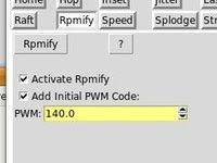 Now, the really clever bit. You COULD post-process the Gcodes to substitute all the PWM speed codes (M 108 S) codes for RPM speed codes (M 108 R). However, you can instead add a script to do this automatically in Skienforge. This feature can also be turned on/off via check box. The script has instructions for installation right in it. The first step tells you where to copy the script to. The second instruction adds the script functionality to the menu. Get the script HERE.
Also, one last thing. You might want to set other initializations in the Skienforge profile you're working on. Here's how...
Go to .../replicatorG/skein_engines/skienforge-35/skienforge_application/prefs
Make a copy of one of the Thing-o-matic profiles that use an HBP, then rename it SF35-CupcakeWithMk6-HBP. Inside the directory structure, there should be a directory called "alterations" with a file called "start.gcode". I found it was helpful to take out the "homing" commands since my build area is smaller than a Thing-o-matic. If not, when the build starts, the platform will try to move the length of the larger build area with obvious bad consequences.
Once I reached this point, I found my simple shapes came out about as well as using the geared motor and they had the benefit of having fewer strings. However, raftless prints were disappointing. So, I made some tweaks to the replicator profile but that process is worth a whole different posting!
- Print out a stepper board bracket so the stepper board can mount over the extruder board. (I tried having Makerbot make the holes in the correct spot but I finally just drilled some mounting holes manually)
- Take apart mk5 extruder. Then use mk6 plates and new stepper motor.
- Hardwire in a fan to the unused 4-pin connector from the power supply. I didn't bother putting mine on a switch so the fan just stays on when power supply is on. Use a volt meter to find the correct voltage for the fan.
- Plug in stepper motor to 12V supply. Then calibrate the stepper motor pot voltage values as described HERE
- Make a custom control cable to connect stepper board to extruder board.
- Use Ubuntu Linux 10.10 and download replicatorG24.
- Make a new .xml "cupcake MK6 with HBP profile" file with stepper motor .xml tags in it (see below)
- download precompiled firmware for extruder board and put into correct place (see below).
- Make reference to it so I can use Replicator program to upload firmware to the extruder board (see below)
- Install rpmify script so post processing can substitute geared motor for stepper motor Gcodes (see below)
- Edit the "start.gcode" file (see below)
- Make a new Replicator profile that works using the new stepper motor.
 For mounting, I recycled my DC bracket I used for the earlier H-bridge problem. Fortunately, the boards were practically the same size. As for standoffs, I found using 6/32 screws with cut tubing for standoffs works well. Don't bother buying tubing. You can use a bit of tubing that comes with the makerbot reel holder.
 Wire-wrapped connections should be wired to make the equivalent circuit as described in this diagram HERE. If you're lucky enough to have some ribbon cable with with dip connectors on each end, cut the ribbon cable in half, then glue the two dip connectors together with superglue. The pins plus the use of a wire-wrap tool make a nice break-out box. That way, there is no soldering needed plus it's easy to troubleshoot and correct if the pin-outs are wrong. I also found using the edge of a 6 pin connector on the extruder's 3 pin connector is easier than soldering together a 3-pin connector to ribbon cable. Also, by accident, I discovered getting pins 7 & 8 reversed makes the circuit act like the motor has either noise problems or a firmware problem. Once I discovered that, I got out the wire wrap tool and was able to quickly correct that connection. Since then, I've had NO noise problems!
Now, for the software changes. I'm using Ubuntu Linux 10.10 with a downloaded version of ReplicatorG ver.24 . Also, remember to make sure you're using JAVA 1.5 and Python 2.5. There are several really handy pages to refer to:
http://wiki.makerbot.com/stepstruder-mk6-with-gen3
http://wiki.makerbot.com/stepper-driven-extruder#toc12
So, let's first make "Cupcake with HBP and Makerbot MK6 stepstruder" appear as a profile choice in the menu. This is important since we're going to be turning on a GUI control not normally seen if a Cupcake is just using a geared motor. To do so, go into the ReplicatorG directory structure. Go to the "machines" folder. You'll see all the profiles available. Let's make a copy of the "cupcake.xml" and call it "cupcakeWithMK6.xml" Then, in text editor, find the .xml "tool" tags
name="Mk6" stepper" type="extruder" material="abs" motor="true" fan="true" heater="true" heatedplatform="true" motor_steps="1600" default_rpm="1.9"
We now need to make our extruder board be able to drive a stepper. So, we'll need to upload a new version of firmware to the extruder board. We COULD install all the packages required to compile our own firmware, then upload it to our board manually. Fortunately, we don't need muck about doing that! A very nice person compiled firmware that works great with the MK6 stepper. If you are using Linux and have GIT, you can download the Koenkooi pre-compiled firmware HERE. I use the pre-compiled hex file version 2.5. To install using a file manager, make sure you can view hidden files. Place this downloaded hex file the ".replicatorg" directory which is located in the user's home directory (usually this directory is above the desktop directory)
Now, make the firmware entry appear in the ReplicatorG firmware menu. Edit the "firmware.xml" file. There should be entries for other firmware choices that would appear in the ReplicatorG "firmware" menu items. Just make another "firmware" tag to point the hex file you just downloaded.
Once the firmware upload capability is in ReplicatorG, just take the programming cord, plug it into the extruder board, then use the menu to upload the pre-compiled firmware to it. Easy!
Inside ReplicatorG, Skienforge also needs to be adjusted. I've decided to only configure the Skienforge35 settings. That means when I generate Gcode, I pick Skienforge35 rather than going with the default Gcode generator.
 Now, the really clever bit. You COULD post-process the Gcodes to substitute all the PWM speed codes (M 108 S) codes for RPM speed codes (M 108 R). However, you can instead add a script to do this automatically in Skienforge. This feature can also be turned on/off via check box. The script has instructions for installation right in it. The first step tells you where to copy the script to. The second instruction adds the script functionality to the menu. Get the script HERE.
Also, one last thing. You might want to set other initializations in the Skienforge profile you're working on. Here's how...
Go to .../replicatorG/skein_engines/skienforge-35/skienforge_application/prefs
Make a copy of one of the Thing-o-matic profiles that use an HBP, then rename it SF35-CupcakeWithMk6-HBP. Inside the directory structure, there should be a directory called "alterations" with a file called "start.gcode". I found it was helpful to take out the "homing" commands since my build area is smaller than a Thing-o-matic. If not, when the build starts, the platform will try to move the length of the larger build area with obvious bad consequences.
Once I reached this point, I found my simple shapes came out about as well as using the geared motor and they had the benefit of having fewer strings. However, raftless prints were disappointing. So, I made some tweaks to the replicator profile but that process is worth a whole different posting!
Sunday, March 20, 2011
A bad extruder motor?
For the heck of it, I decided to find out why the motor failed. There was a remote possibility the motor gears might just be jammed. Maybe a bit of oil is all it needs! So, I took it off the extruder assembly. The gear box in front of the motor seemed OK.I then separated the gearbox from the motor. I then powered up the motor with a 9V transistor battery. It seemed to run but it was a bit rough. However, since I have no idea how the motor normally operates, I decided to put it all back together and give it another go. Just for good measure, I also decided to put a lighter grade of oil in the gearbox. A 9V battery was still able to turn the motor once the gearbox was reassembled.
I then re-installed the motor. Using the control panel, the motor-gearbox seemed to have no trouble extruding a steady stream of plastic. It also started and stopped OK many times under the control panel. However, when doing a print job, it would still fail unpredictably when doing a raft. Sometimes it would make it as far as the 2nd or 3rd layer. However, I could not get a reliable extrusion past that point no matter the thumbwheel setting was. Taking some measurements showed that the DC driver circuit seemed to be doing it's job and the status lights on the extruder board are also helpful in showing that the circuit section is either working or not. Taking apart the motor showed that the gearbox seems OK. However, I've still declared the motor officially broken.
By broken, the motor rotates without it's gearbox, but it runs rough. I suspect when the motor is at a rough part, this causes the extruder board to sense something strange is going on. So, the extruder board then shuts the channel down. This is easily observed when lights on the extruder channel stop working. I eventually learned that shutdown can be prevented by going into Skienforge to put a smaller maximum extrusion value. If the motor is stalled, voltage levels are still maintained so it seems that the board is doing it's job. However, all that doesn't matter since the motor doesn't rotate! What is interesting is that the same behavior was seen even with the add-on driver board. So, maybe channel shutdown is caused by a noise issue? Maybe the motor momentarily shorts (or opens)? Hard to say without having another known good motor to compare this behavior to.
Of course, Makerbot is out of these replacement motors. The community has mentioned that the geared motors don't hold up well and even Makerbot admitted that they now know they had a bad batch of motors go out the door. Makerbot does not offer these motors anymore. So, I ordered a batch direct from Kysane. Since they have a large minimum order, I'll be selling what I don't use via Ebay. Note, this order was en-route PRE-Earthquake so these motors are NOT radioactive Yay!!
Saturday, March 19, 2011
DC driver board is built, works nice, but now there is another problem.
 Ok, so I finally build and add on the DC driver board. As you can see, I did some part substitutions. It's ugly but it w seems to work. Unfortunately, on the 3rd print, the plastic feedstock had a problem being pulled into the extruder. I guess that's what I get for leaving my bot alone for a few minutes! By the time I got to the printer to untangle it, not only was there no plastic being printed but I also noticed a faint electrical smell too. Never good! The new extruder board's heavier H-Bridge chip was really hot! So, I'm thinking if I'm lucky, maybe the chip simply went into thermal shutdown. If so, maybe a heat sink is all I would need! Fortunately, when I built the board, I used a socket and I have an extra chip if I need it.
So, let's see what damage was done. Let everything cool. Untangle the plastic, disengage the pinch wheel so the motor is free to move, then do some testing. I reset everything. I figure, maybe the driver chip fried. So, I use a volt meter to check the DC output using the software control panel. 6V at half speed, 10V at almost full speed. Using a multimeter, I decide the driver circuit is probably OK. So, I test the resistance of the motor by itself. It reads 1 ohm which is really low even for a motor. According to this article they should read more like 47 ohms. So, I'm expecting that the motor may have an internal short.
Saturday, March 5, 2011
AAARGH! Another board problem.
 For the past month, my Makerbot Cupcape extruder had progressively more trouble extruding. After some research, I found others had this problem too. It seems to be due to an undersized "H-bridge" chip driving more than it should.
 A few weeks ago, I decided I should have another complete set of Gen3 electronics on hand just in case I had a failure such as this. That way, I could swap boards if one went bad and not be "down" while I repaired the other board. However, the Gen3 board set has been consistently out of stock at Makerbot for a couple months. In the mean time, I'm not completely out of options. It turns out that there are two extruder motor driver circuits! In Skienforge, going into the extruder board settings, you can change from the primary extruder driver (using 1A, 1B) to the secondary driver (using 2a, 2b). Still, that just solves the symptom, not the problem. The real cause of this might just be my motor is drawing too much. For now, I've hooked up the extruder motor to the secondary extruder driver circuit. But I'm thinking that this failure is likely to happen again. So, what are my longer term options?
Option 1) Install the Makerbot Stepstruder upgrade kit. Even though this upgrade is listed as "Experimental" I have a reasonable expectation that this would work. My order is in, but it will be a while before this solution arrives.
Option 2) Replace this chip with another of the same kind. I probably could rush order the chip from Digikey and try my hand at soldering it in. However, even if I did accomplish this tricky surface mount soldering operation, it's likely the new chip might just blow out again!
Option3) Replace the wimpy chip with something a little heavier. Fortunately, someone else decided this was a good idea too. So, they documented the fix!
http://wiki.makerbot.com/gen3-hbridge-fix. Makerbot even lists the kit on their site!
The problem with option3 is that Makerbot is now out of those parts too! Fortunately, they still had the bare board available. So, between what I have in stock in my workshop, a rush order from Digikey and a trip down to Radio Shack, I now have the parts needed to make that repair. Since my secondary circuit still works, I'll be printing out a bracket so I can mount this secondary board directly above the extruder board. Hopefully, my secondary extruder circuit will last long enough to do that print!
I am disappointed in the supply problems Makerbot seems to have. As you may have guessed, buying components from several places then paying retail prices per-component, has boosted the cost of this fix by quite a bit.At times like this, I'm reminded of the Monty Python Cheese Shop.
http://www.youtube.com/watch?v=B3KBuQHHKx0
However, in spite of these problems, Makerbot still has one really good thing going for it. It's the fact that the device is an open design. That means I have a fighting chance of fixing this myself. If this product was proprietary with no schematics and secret firmware, and the company went out of business, I would be totally out of luck. Even though the Gen3 electronics apparently aren't very robust, they are at least an open design with a vibrant user community. That means this repair is annoying rather than impossible.
Thursday, March 3, 2011
Using the Cupcake automated build platform
 I finally assembled the build platform hoping I could start kicking out several parts at a time. Unfortunately, I was in a hurry and I assembled the belt inside out. But hey, stupid me, I decided to go with it anyway - and discovered I couldn't print anything since the belt surface was too slippery! Turns out the plastic has two sides. One side is very slippery and the other is not as much. So, word to the wise. If when you're done, the stripe appears on the right as in the photo...you did it wrong too.
The other parts of the build were rather straightforward in having images for every major step. That is, except for one. I couldn't find a photo where the build platform motor plugs into a board. I eventually figured it out. How? Well, when looking at the instructions, it turns out, I had to read rather than just look at pictures. So, for those of us who like looking at pictures rather than reading, I made a quick reference image to show what wires go to what connectors.
 Anyway, the second time I used the platform with the belt on the proper way, all did not go well. The makerbot briefly lost it's brains and tried forcing the hot extruder head through the platform. This then melted the plastic conveyor belt. The next instruction then dragged the extruder head over the belt making a giant gouge in the belt and also dented the metalized platform.
So, rather than repair the conveyor, I've decided to just use the heated build platform by itself. Someday, I may go back to using the build platform but I'll need to stock up on some spare belts first!
Tuesday, February 22, 2011
From useless to useful!
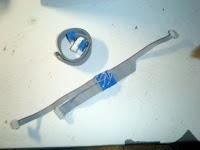
 Yes, I sometimes do trash pick. Such was the case with this nice looking tripod that was being thrown out. It was missing a small but critical part called a quick-release. Normally, that would make a tripod like this rather useless. But not for me! After taking some measurements, I designed a basic plate and then printed! Now that I have a plate, I'll only need to stop by the hardware store to buy a screw that fits the camera mount. Sweet!
Sunday, February 13, 2011
A print from Sketchup
I decided to print a gear using Google Sketchup. To generate a sample gear, I used the gear add-on module. To use it, I had to back down to version 7.1 rather than 8.0. To export the design to Skienforge, I had to use a DFX exporter add-on too. To install both components, simply download and save to the Google Sketchup directory called "plugins". Once installed, the new controls appear in the Sketchup pull down menu.
The components are available in multiple places, but also available HERE
 Above is the progression of prints I tried. The night I printed, the Cupcake was being rather fussy. When I last turned it off, the last print it did was a pretty good calibration cube. Unfortunately, after sitting nearly a week, I found the printer was not quite a "turn on and print" device. For some reason, the extruder motor would not energize. Pushing the "reset" button on the motherboard solved that issue. I also have the impression the rods have become a little wobbly, possibly due to being under constant tension from the z-stage drive belt. It was clear from the raft on the first print that I was going to get a stringy mess so I aborted the first print. What I think happened was that the nozzle was clogged with something. I'm guessing either dust or a cat hair. Fortunately, I was able to flush out whatever it was by going to the control panel and running the nozzle at 255 until the plastic started coming out nicely again. The next print came out better, but still, not great. After manipulating the Gcode settings having to do with layer thickness and density, the next print came out much better. A copy was then made which I consider would be a usable end product. I can see right now that one really nice upgrade would be some stiffer z-rods and of course a MK6 extruder upgrade. However, for now, the printer seems to do what I want it to do.
Subscribe to:
Posts (Atom)